Arduino – Communication

Hundreds of communication protocols have been defined to achieve this data exchange. Each protocol can be categorized into one of the two categories: parallel or serial.

Parallel Communication

Parallel connection between the Arduino and peripherals via input/output ports is the ideal solution for shorter distances up to several meters. However, in other cases when it is necessary to establish communication between two devices for longer distances it is not possible to use parallel connection. Parallel interfaces transfer multiple bits at the same time. They usually require buses of data – transmitting across eight, sixteen, or more wires. Data is transferred in huge, crashing waves of 1’s and 0’s.


Advantages and Drawbacks of Parallel Communication

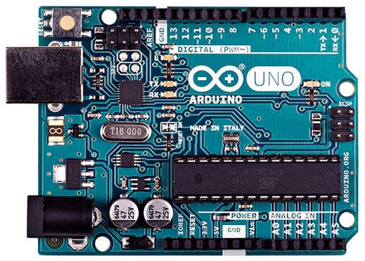
Parallel communication certainly has its advantages. It is faster than serial, straightforward, and relatively easy to implement. However, it requires many input/output (I/O) ports and lines. If you have ever had to move a project from a basic Arduino Uno to a Mega, you know that the I/O lines on a microprocessor can be precious and few. Therefore, we prefer serial communication, sacrificing potential speed for pin real estate.

Serial Communication Modules

Today, most Arduino boards are built with several different systems for serial communication as standard equipment.

Which of these systems are used depends on the following factors −

  • How many devices the microcontroller has to exchange data with?
  • How fast the data exchange has to be?
  • What is the distance between these devices?
  • Is it necessary to send and receive data simultaneously?

One of the most important things concerning serial communication is the Protocol, which should be strictly observed. It is a set of rules, which must be applied such that the devices can correctly interpret data they mutually exchange. Fortunately, Arduino automatically takes care of this, so that the work of the programmer/user is reduced to simple write (data to be sent) and read (received data).

Types of Serial Communications

Serial communication can be further classified as −

  • Synchronous − Devices that are synchronized use the same clock and their timing is in synchronization with each other.
  • Asynchronous − Devices that are asynchronous have their own clocks and are triggered by the output of the previous state.

It is easy to find out if a device is synchronous or not. If the same clock is given to all the connected devices, then they are synchronous. If there is no clock line, it is asynchronous.

For example, UART (Universal Asynchronous Receiver Transmitter) module is asynchronous.

The asynchronous serial protocol has a number of built-in rules. These rules are nothing but mechanisms that help ensure robust and error-free data transfers. These mechanisms, which we get for eschewing the external clock signal, are −

  • Synchronization bits
  • Data bits
  • Parity bits
  • Baud rate

Synchronization Bits

The synchronization bits are two or three special bits transferred with each packet of data. They are the start bit and the stop bit(s). True to their name, these bits mark the beginning and the end of a packet respectively.

There is always only one start bit, but the number of stop bits is configurable to either one or two (though it is normally left at one).

The start bit is always indicated by an idle data line going from 1 to 0, while the stop bit(s) will transition back to the idle state by holding the line at 1.


Data Bits

The amount of data in each packet can be set to any size from 5 to 9 bits. Certainly, the standard data size is your basic 8-bit byte, but other sizes have their uses. A 7-bit data packet can be more efficient than 8, especially if you are just transferring 7-bit ASCII characters.

Parity Bits

The user can select whether there should be a parity bit or not, and if yes, whether the parity should be odd or even. The parity bit is 0 if the number of 1’s among the data bits is even. Odd parity is just the opposite.

Baud Rate

The term baud rate is used to denote the number of bits transferred per second [bps]. Note that it refers to bits, not bytes. It is usually required by the protocol that each byte is transferred along with several control bits. It means that one byte in serial data stream may consist of 11 bits. For example, if the baud rate is 300 bps then maximum 37 and minimum 27 bytes may be transferred per second.

Arduino UART

The following code will make Arduino send hello world when it starts up.

void setup() {
   Serial.begin(9600); //set up serial library baud rate to 9600
   Serial.println("hello world"); //print hello world
}

void loop() {

}

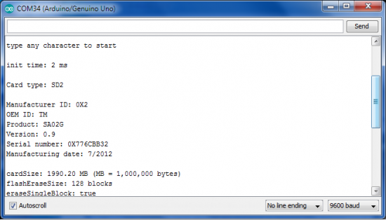
After the Arduino sketch has been uploaded to Arduino, open the Serial monitor at the top right section of Arduino IDE.

Type anything into the top box of the Serial Monitor and press send or enter on your keyboard. This will send a series of bytes to the Arduino.

The following code returns whatever it receives as an input.

The following code will make Arduino deliver output depending on the input provided.

void setup() {
   Serial.begin(9600); //set up serial library baud rate to 9600
}

void loop() {
   if(Serial.available()) //if number of bytes (characters) available for reading from { 
      serial port
      Serial.print("I received:"); //print I received
      Serial.write(Serial.read()); //send what you read
   }
}

Notice that Serial.print and Serial.println will send back the actual ASCII code, whereas Serial.write will send back the actual text. See ASCII codes for more information.


Arduino Interrupts

Interrupts stop the current work of Arduino such that some other work can be done.

Suppose you are sitting at home, chatting with someone. Suddenly the telephone rings. You stop chatting, and pick up the telephone to speak to the caller. When you have finished your telephonic conversation, you go back to chatting with the person before the telephone rang.

Similarly, you can think of the main routine as chatting to someone, the telephone ringing causes you to stop chatting. The interrupt service routine is the process of talking on the telephone. When the telephone conversation ends, you then go back to your main routine of chatting. This example explains exactly how an interrupt causes a processor to act.

Interrupts


Important features

Here are some important features about interrupts −

  • Interrupts can come from various sources. In this case, we are using a hardware interrupt that is triggered by a state change on one of the digital pins.
  • Most Arduino designs have two hardware interrupts (referred to as “interrupt0” and “interrupt1”) hard-wired to digital I/O pins 2 and 3, respectively.
  • The Arduino Mega has six hardware interrupts including the additional interrupts (“interrupt2” through “interrupt5”) on pins 21, 20, 19, and 18.
  • You can define a routine using a special function called as “Interrupt Service Routine” (usually known as ISR).
  • You can define the routine and specify conditions at the rising edge, falling edge or both. At these specific conditions, the interrupt would be serviced.
  • It is possible to have that function executed automatically, each time an event happens on an input pin.

The main program is running and performing some function in a circuit. However, when an interrupt occurs the main program halts while another routine is carried out. When this routine finishes, the processor goes back to the main routine again.

Seeeduino or Arduino?

Seeed has recently updated its open source development board Seeeduino V4 into a V4.2 model with shrunken price tag — just under $7 — for what’s essentially a full-sized Arduino Uno clone with a superset of the Uno’s expansion capabilities.

Seeeduino or Arduino 1

Like the Seeeduino V4, the V4.2 is built around the same ATmega328P MCU (clocked at 16MHz) that’s used on the Arduino Uno, and offers an Uno-compatible topside expansion bus. Additionally, the Seeduino V4 and V4.2 both supplement the Uno’s I/O capabilities with connectors for interfacing with Grove modules: two on the V4, and three on the V4.2. Both boards are 115 x 78 x 25mm in size and have mounting holes that match those of the Uno.

Both Seeeduino models are also compatible with the Arduino Uno bootloader, and can be programmed and powered through their micro-USB connectors. Power can also be supplied through the dedicated power jack, which supports 7 to 15V DC input.

Seeed Studio lists these differences between both Seeeduino V4x boards and the Arduino Uno:

  • Use of a micro-USB port for powering and programming the board
  • On-board Grove module interface connectors
  • A switch for choosing between 3.3V and 5V DC power input
  • Use of a DC-to-DC converter instead of an LDO (Low DropOut regulator), for enhanced efficiency
  • Various improvements to circutry

The Seeeduino V4.2’s schematic and other documentation are available for download from its wiki page.

What’s your favourite?

Seeeduino or Arduino 2

Artificial Intelligence on Arduino – An invincible Tic Tac Toe Player

Tic Tac Toe Arduino Game

It is hard to imagine an Arduino with only 2k RAM capable of playing tic tac toe better then most of us. That is right, an unbeatable Tic Tac Toe player with a memory footprint of less than 2 kilobytes. In this tutorial we will implement a perfect Tic Tac Toe player which will never lose, it can only win or draw. – Arduino

Tic Tac Toe Arduino Game

In such simple games, where the amount of possible moves are limited and respectively small, the minimax algorithm comes very handy. The minimax algorithm works best when the end of the game can be predicted. A board game such as tic tac toe is relatively simple with only 9 steps. So the decision tree off all possible moves needs to have a depth of only 9 levels. That said, the total permutations amount to 9! (Factorial) which is 362,880 although there are many games that end before the grid is filled up so that number is actually much less.

So, we at Runtime Projects decided to have a go with this by creating an invincible Tic Tac Toe player. The game will be outputted using the serial port so as not to complicate matters. However feel free to use this code to create your own version with LCDs or LEDs. We are not going into the details of implementing the algorithm here. This is pure C programming with a little thought about keeping a very small memory footprint. To make the game a little interesting, we have assigned a difficulty level for the AI to give us humans, a chance to win. The difficulty level is set from 1 to 8. 1 being the easiest and 8 being impossible. First the user is asked to state who is starting the game. Then, placing the X’s is simply entering the number of the box from 0 to 8.

Download the code from here

Arduino with Keypad Tutorial

A keypad is one of the most commonly used input devices in microprocessor applications. In a standard keypad wired as an X-Y switch matrix, normally-open switches connect a row to a column when pressed. If a keypad has 12 keys, it is wired as 3 columns by 4 rows. A 16 key pad would have 4 columns by 4 rows. Some time ago, I bought a couple of 3×4 membrane keypads from eBay. As usual it’s packed with zero documentation, thus it took couple of hours to get to work. Anyway the keypad is a perfect blend of art and technology with a price tag far below rubies! – Arduino

Arduino with Keypad Tutorial 1

This little article is designed to help you get started with your new microcontroller + keypad project so let’s start. Following figure shows the internal structure and pin notation of the 3×4 keypad used for the experiment. The drawing is the result of an obscene amount of research work because I really wanted to make an error-free guide for the project we are working on.

Arduino with Keypad Tutorial 2

Here is the same information in a textual way; keypad columns C1-C2-C3 are routed to pins 3,1,5 and rows R1-R2-R3-R4 are routed to pins 2,7,6,4 located at the end of the 7-pin flexible cable. Much more clear now?

Arduino with Keypad Tutorial 3

So now you can see how the button presses can be translated into electrical data for use with a microcontroller. We can now start the real experiment with as Arduino Uno by wiring up the keypad to the Arduino in the following/like manner:

  • Keypad pin 1 to Arduino digital 3 //C2
  • Keypad pin 2 to Arduino digital 5 //R1
  • Keypad pin 3 to Arduino digital 2 //C1
  • Keypad pin 4 to Arduino digital 8 //R4
  • Keypad pin 5 to Arduino digital 4 //C3
  • Keypad pin 6 to Arduino digital 7 //R3
  • Keypad pin 7 to Arduino digital 6 //R2

Since keypads are available from many retailers make sure you can get the data sheet as this will make the task easier when wiring them up. If your keypad is different, take note of the lines in the sketch from //keypad type definition, as you need to change the numbers in the arrays rowPins[ROWS] and colPins[COLS]. You should enter the digital pin numbers connected to the rows and columns of the keypad respectively. Example from Arduino playground:

  1. #include “Keypad.h”
  2. // keypad type definition
  3. const byte ROWS = 4; //four rows
  4. const byte COLS = 3; //three columns
  5. char keys[ROWS][COLS] = {
  6. {‘1’,‘2’,‘3’},
  7. {‘4’,‘5’,‘6’},
  8. {‘7’,‘8’,‘9’},
  9. {‘*’,‘0’,‘#’}
  10. };
  11. byte rowPins[ROWS] = {5, 6, 7, 8}; //connect to the row R1-R4 pinouts of the keypad
  12. byte colPins[COLS] = {2, 3, 4}; //connect to the column C1-C3 pinouts of the keypad

Next is a project example, where the Arduino is instructed to do something based on a correct key (secret number) being entered into the keypad, probably the most demanded application of the keypad. For this, just wire up the hardware (arduino+keypad) as described earlier.

Arduino with Keypad Tutorial 4

Although the code is an entry-level one, it includes a secret key option that will need to be entered on the keypad. The Serial Monitor will tell whether the numerical-key inputted to the keypad is correct or not. To activate and deactivate the lock, the user must press * and then the secret key, followed by #. Okay, copy-paste, compile and upload this sketch (adaptation of a work by John Boxall) as usual:

  1. #include “Keypad.h”
  2. const byte ROWS = 4; // four rows
  3. const byte COLS = 3; // three columns
  4. char keys[ROWS][COLS] =
  5. {
  6. {‘1’,‘2’,‘3’ },
  7. {‘4’,‘5’,‘6’ },
  8. {‘7’,‘8’,‘9’ },
  9. {‘*’,‘0’,‘#’ }
  10. };
  11. byte rowPins[ROWS] = {5, 6, 7, 8};
  12. byte colPins[COLS] = {2, 3, 4};
  13. Keypad keypad = Keypad( makeKeymap(keys), rowPins, colPins, ROWS, COLS );
  14. char KEY[4] = {‘1’,‘2’,‘3’,‘4’}; // default secret key
  15. char attempt[4] = {0,0,0,0};
  16. int z=0;
  17. void setup()
  18. {
  19. Serial.begin(9600);
  20. }
  21. void correctKEY() // do this if the correct KEY is entered
  22. {
  23. Serial.println(” KEY ACCEPTED…”);
  24. }
  25. void incorrectKEY() // do this if an incorrect KEY is entered
  26. {
  27. Serial.println(“KEY REJECTED!”);
  28. }
  29. void checkKEY()
  30. {
  31. int correct=0;
  32. int i;
  33. for ( i = 0; i < 4 ; i++ )
  34. {
  35. if (attempt[i]==KEY[i])
  36. {
  37. correct++;
  38. }
  39. }
  40. if (correct==4)
  41. {
  42. correctKEY();
  43. }
  44. else
  45. {
  46. incorrectKEY();
  47. }
  48. for (int zz=0; zz<4; zz++) // clear previous key input
  49. {
  50. attempt[zz]=0;
  51. }
  52. }
  53. void readKeypad()
  54. {
  55. char key = keypad.getKey();
  56. if (key != NO_KEY)
  57. {
  58. switch(key)
  59. {
  60. case ‘*’:
  61. z=0;
  62. break;
  63. case ‘#’:
  64. delay(100); // added debounce
  65. checkKEY();
  66. break;
  67. default:
  68. attempt[z]=key;
  69. z++;
  70. }
  71. }
  72. }
  73. void loop()
  74. {
  75. readKeypad();
  76. }

If your compiler raises an error “keypad does not name a type”, probably you have not installed the required Keypad Library correctly. If you still have the problem after downloading and installing the library, just drop me a line here in the comments.

Note that the good old 3×4 telephone keypad from your junk box can also be used for this project. Like most keypads, it is wired as an X-Y switch matrix, the normally-open switches connect a row (R) to a column (C) when pressed. Next figure shows the pin assignments of a generic 3×4 telephone keypad:

Arduino with Keypad Tutorial 5

If you don’t know which pin represents which row or column, you have to fiddle the “rummy” keypad using your analog multimeter. It might take hours to get to work, be patient!

Arduino with Keypad Tutorial 6

Note: At the middle of this experiment, I got another 3×4 keypad from an eBay seller with the “true” Arduino compatible pin-out (see figure shown below). If you are using this type, it would be better to change the arrays rowPins[ROWS] and colPins[COLS] in the sketch as indicated.

Arduino with Keypad Tutorial 7

Also Check:

Arduino I2C LCD Backpack Introductory Tutorial

Assume that you are moving towards a complex microcontroller project bundled with blinkers, beepers, and a display panel. To link a standard 16×2 LCD directly with the microcontroller, for instance Arduino, you would need atleast 6 I/O pins to talk to the LCD. However, if you use an LCD module with I2C interface, you only need 2 lines to process the display information. Now a days, it is not necessary to buy an expensive I2C LCD for this task because readymade serial backpack modules for standard LCDs are available at reasonable rates. You can use them with LCD modules that have a

compatible interface with various screen sizes by attaching to the back of the LCD module. This allows connection to your Arduino (or other microcontroller) using only four channels. Yippee! – Arduino

Arduino I2C LCD Backpack Introductory Tutorial 1


I2C LCD Backpack

Hitachi’s

based 16×2 character LCD are very cheap and widely available, and is an essential part for any project that displays information. Using the LCD backpack, desired data can be displayed on the LCD through the I2C bus. In principle, such backpacks are built aorund

(from NXP) which is a general purpose bidirectional 8 bit I/O port expander that uses the I2C protocol. The

is a silicon CMOS circuit provides general purpose remote I/O expansion (an 8-bit quasi-bidirectional) for most microcontroller families via the two-line bidirectional bus (I2C-bus). Note that most backpack modules are centered around

T (SO16 package of

in DIP16 package) with a default slave address of 0x27. If your backpack holds a

AT chip, then the default slave address will change to 0x3F. In short, your backpack is based on

T and the address connections (A0-A1- A2) are not bridged with solder it will have the slave address 0x27.

Arduino I2C LCD Backpack Introductory Tutorial 2

Reference circuit diagram of an Arduino-compatible LCD backpack is shown below. What follows next is information on how to use one of these inexpensive backpacks to interface with a microcontroller in ways it was exactly intended.

Arduino I2C LCD Backpack Introductory Tutorial 3

I2C LCD Display

Now let’s get started. At first you need to solder the backpack to your LCD module. Ensure that the backpack pins are straight and fit in the LCD module, then solder in the first pin while keeping the backpack in the same plane with the LCD. Once you have finished the soldering work , get four jumper wires and connect the LCD module to your Arduino as per the instruction given below.

Arduino I2C LCD Backpack Introductory Tutorial 4

Arduino Setup

For this experiment it is necessary to download and install the “Arduino I2C LCD” library. First of all, rename the existing “LiquidCrystal” library folder in your Arduino libraries folder as a backup, and proceed to the rest of the process.
Next, copy-paste this example sketch for the experiment into the blank code window, verify, and then upload.

  1. /*
  2. Project: I2C LCD Backpack Arduino Experiment
  3. By: T.K.Hareendran
  4. For: http://www.arduinopoint.wordpress.com
  5. Includes: Library from https://bitbucket.org/fmalpartida/new-liquidcrystal/downloads*
  6. Hardware/Controller: See article
  7. Software/Sketch: Precisely adapted – Ref: Internet
  8. Date: December 2015
  9. */
  10. #include “Wire.h” // For I2C
  11. #include “LCD.h” // For LCD
  12. #include “LiquidCrystal_I2C.h” // Added library*
  13. //Set the pins on the I2C chip used for LCD connections
  14. //ADDR,EN,R/W,RS,D4,D5,D6,D7
  15. LiquidCrystal_I2C lcd(0x27,2,1,0,4,5,6,7); // 0x27 is the default I2C bus address of the backpack-see article
  16. void setup()
  17. {
  18. // Set off LCD module
  19. lcd.begin (16,2); // 16 x 2 LCD module
  20. lcd.setBacklightPin(3,POSITIVE); // BL, BL_POL
  21. lcd.setBacklight(HIGH);
  22. }
  23. void loop()
  24. {
  25. lcd.home (); // Set cursor to 0,0
  26. lcd.print(“protolabz”); // Custom text
  27. lcd.setCursor (0,1); // Go to home of 2nd line
  28. lcd.print(millis());
  29. delay(1000); // Blinks of backlight
  30. lcd.setBacklight(LOW); // Backlight off
  31. delay(500);
  32. lcd.setBacklight(HIGH); // Backlight on
  33. delay(1000);
  34. }

If you are 100% sure that everything is okay, but you don’t see any characters on the display, try to adjust the contrast control pot of the backpack and set it a position where the characters are bright and the background does not have dirty boxes behind the characters. Following is a partial view of author’s experiment with the above described code. Since the display used by the author is a very clear bright “black on yellow” type, it is very difficult to get a good catch due to polarization effects.

Arduino I2C LCD Backpack Introductory Tutorial 5

Lab Note

The hardware configuration described have been tested with an Arduino UNO R3, a 16×2 LCD, and an I2C LCD backpack purchased from an eBay seller. Further, the example sketch has been fully tested with a 4 bit interface as described using Arduino IDE0022. Source code for the library used here and its official documentation can be downloaded from the download section of this repository which comes in source and with examples that will get you started. Additionally you have a full description of the library in the docs folder in HTML format that you can browse. Have fun!

Layman’s Camera Remote Control

It’s sensible to use a remote control when your camera is mounted on a tripod, especially when you are using slow shutter speeds. The stability of even a high-quality tripod can be compromised if you touch and jostle the camera while taking a shot. A camera remote control enables a more hands-off approach. – Arduino

An Insight

The core of this project is a simple circuit that connects to the camera’s remote shutter release. At a basic level, this just involves connecting two of the pins used for the camera remote together to simulate pressing the button on the remote. This project uses the Canon N3 connector, but you can achieve the same results with other connectors, too. Canon’s low-end DSLR cameras use an E3 socket (a 2.5-mm stereo socket) to connect remote shutter releases to the camera. However, the mid- to high-end DSLR cameras use Canon’s proprietary N3 socket.

Fig. 1 shows the N3 socket on a Canon camera body, its electrical connections, and a bare N3 connector. For the N3 interface, connecting the focus pin to the ground (common) pin is equivalent to a half-press of the shutter button, whereas connecting the shutter pin to the ground pin is equivalent to a full press.

Layman_s Camera Remote Control 1

A Simple Start

The easiest way to construct a cable for this project is to obtain a wired shutter release cable with an N3 connector interface. You can buy the more expensive cable from the camera manufacturer or find a cheaper alternative, which can still work well. Most remote release switches in the cables are made with metal leaves that are designed to make contact with the half-press (focus) wire touching ground (common). Then, the full-press (shutter) wire makes contact with both the ground and half-press. You can make your own shutter release cable with the help of a spare N3 connector and a homemade button switch (see Fig. 2).

Layman_s Camera Remote Control 2

Now that you know how the N3 interface works, all you need to do is wire a circuit that allows you to switch the yellow (F) and/or pink (S) wires to ground (G). The focus wire may be useless if you can focus the camera before it takes a picture, but it is included here for completeness. The completed electrical wiring is pictured below (Fig. 3). Make sure to clean up any loose strands of copper wire so that you don’t accidentally make contact between the three switching points.

Layman_s Camera Remote Control 3

Add Some Electronics

The solution presented above is really simple and straightforward — a small plastic box with a two-position button switch. The next solution is a more advanced module, which you can easily connect to a microcontroller to trigger the shutter on a Canon DSLR camera that has an N3 connector.

Furthermore, you can attach various sensors/transducers to enhance the shooting experience. For example, by adding a sound sensor, vibration monitor, or a motion detector/laser trip wire, you can snap a picture every time you say a word, if something falls, or if someone walks down the hallway!

The little circuit works from 3.3 V to 5.0 V DC and is wired around a quad bilateral switch

(IC1). The circuit has been kept simple for reliability’s sake. The whole of the circuit fits onto a single-sided Perfboard/PCB and is easy to set inside most prototype/custom enclosures. The 4-pin connector J1 is for the microcontroller interface, while the second 4-pin connector J2 can be attached to the N3 connector/cable. The design uses just two bilateral switches of IC1 to fire the camera’s shutter — one for the half-press and one for the full-press signals.

It is perfectly acceptable to use just one signal (shutter) to fire the camera, although with some camera bodies, it may be possible to achieve faster shutter speeds by “cooking” the camera with a short half-press before the full-press. Logic-high (H) inputs on the focus and shutter pins of J1 will set off the focus and shutter operation of the camera linked through the J2-N3 connector.

Layman_s Camera Remote Control 4


4066 datasheet

Arduino Fun

It’s possible to use Arduino to talk to the camera through the circuit shown above. Here is a “test” sketch to control the operation via the USB cable using the serial monitor. The functionality is very rudimentary and the sketch is pretty self-explanatory with the few comments that are included. All the sketch does is focus when you hit the “F” key and take a picture when you press the “S” key. See the hardware diagram and software code (sketch) shown below:

Layman_s Camera Remote Control 5


  1. #define FOCUS_PIN 12
  2. #define SHUTTER_PIN 13
  3. void setup()
  4. {
  5. pinMode(FOCUS_PIN, OUTPUT);
  6. pinMode(SHUTTER_PIN, OUTPUT);
  7. digitalWrite(FOCUS_PIN, LOW);
  8. digitalWrite(SHUTTER_PIN, LOW);
  9. Serial.begin(9600); // open serial
  10. Serial.println(“Press ‘f’ to focus and ‘s’ to fire shutter”);
  11. }
  12. void loop()
  13. {
  14. int cmd;
  15. while (Serial.available() > 0)
  16. {
  17. cmd = Serial.read();
  18. switch (cmd)
  19. {
  20. case ‘f’:
  21. {
  22. digitalWrite(FOCUS_PIN, HIGH);
  23. delay(800); // adjust this depending on focus time digitalWrite(FOCUS_PIN, LOW);
  24. break;
  25. }
  26. case ‘s’:
  27. {
  28. digitalWrite(SHUTTER_PIN, HIGH);
  29. delay(2000); // adjust this depending on shot type
  30. digitalWrite(SHUTTER_PIN, LOW);
  31. break;
  32. }
  33. default:
  34. {
  35. Serial.println(“Press ‘f’ to focus and ‘s’ to fire shutter”);
  36. }
  37. }
  38. }
  39. }
download Arduino Sketch

Combining electronics and photography can be fun. One popular use of a remote control is for wildlife photography, where you may not be able to stay physically close to the camera but you still want to have control over your snapshots. As far as I’m aware, you cannot purchase bare N3 connectors from local component vendors. However, a number of cables are available with an N3 connector on one end from online shops like eBay, Amazon, and AliExpress. Or you can try to make your own N3 connector at home using different tricks available over the web. This website offers one example: diff.net/peter/photography/canon_n3_connector_info.shtml.

Finally…

This is not intended to be a complete solution to everything you could possibly want to do; rather, it is a primer on first steps, along with some pointers and ideas on where to go next. Although the proof of concept was successfully tested, the information is provided without warranties, claims of accuracy, or completeness of any sort. Use this information at your own risk!

Also Check:

Build Your Own Radio Beacons

A radio beacon is a wireless device that marks a fixed location and allows direction-finding equipment to locate it. It transmits a continuous or periodic radio signal with limited information content — for example, its identification or location — on a specified radio frequency, which is picked up by direction-finding systems on ships, aircraft, and vehicles to determine the location of the device. Occasionally, the beacon function is combined with some other transmission, like telemetry data or meteorological information. – Arduino

Last summer, I fabricated a radio beacon with the help of some extra components in my junk box. I couldn’t find the schematic drawing/breadboard, so I went ahead and started an advanced design. Now I am waiting for some components from abroad to show up for my prototype; in the meantime, I wanted to share some of my ideas on radio beacons.

The 555 RF Beacon

The RF beacon transmitter presented here is by no means new and has been covered many times, but by using only a 555 timer chip and some other basic components, it keeps the finished circuit small and simple. It’s basically a short-range LW transmitter (an empty-carrier beacon oscillator) with a small wire antenna. Components R1, R2, and C1 control the output frequency of this battery-powered oscillator.

Build Your Own Radio Beacons 1


You can find the transmission of this beacon by tuning a nearby radio to about 230 KHz. Note that, since this beacon lacks the support of an RF output amplifier, its output is limited to a very short distance (5–15 feet). Fortunately, the addition of even a simple RF output amplifier will greatly increase the range of the beacon. You can also mix a tone generator to modulate the carrier so you have a good chance of finding the beacon signal than if you only transmitted an empty carrier.

An Arduino Morse Beacon

The Arduino Morse Beacon project discussed below, while useful, is simply a trivial Morse code generator that delivers the pre-defined beacon message through the Arduino’s D13 output. The sketch below (with built-in Morse table) is actually an adaptation of a noteworthy open-source work by Mark VandeWettering (k6hx@arrl.net). It simply puts a logic-high state (H) on D13 output whenever the keydown should occur and a logic-low state (L) when it is released.

  1. /*
  2. An Arduino Morse Beacon
  3. Adaptation of a work by Mark VandeWettering
  4. Authored & Tested by T.K.Hareendran
  5. */
  6.  
  7.  
  8. struct t_mtab { char c, pat; } ;
  9.  
  10. struct t_mtab morsetab[ ] = {
  11. {‘.’, 106},
  12. {‘,’, 115},
  13. {‘?’, 76},
  14. {‘/’, 41},
  15. {‘A’, 6},
  16. {‘B’, 17},
  17. {‘C’, 21},
  18. {‘D’, 9},
  19. {‘E’, 2},
  20. {‘F’, 20},
  21. {‘G’, 11},
  22. {‘H’, 16},
  23. {‘I’, 4},
  24. {‘J’, 30},
  25. {‘K’, 13},
  26. {‘L’, 18},
  27. {‘M’, 7},
  28. {‘N’, 5},
  29. {‘O’, 15},
  30. {‘P’, 22},
  31. {‘Q’, 27},
  32. {‘R’, 10},
  33. {‘S’, 8},
  34. {‘T’, 3},
  35. {‘U’, 12},
  36. {‘V’, 24},
  37. {‘W’, 14},
  38. {‘X’, 25},
  39. {‘Y’, 29},
  40. {‘Z’, 19},
  41. {‘1’, 62},
  42. {‘2’, 60},
  43. {‘3’, 56},
  44. {‘4’, 48},
  45. {‘5’, 32},
  46. {‘6’, 33},
  47. {‘7’, 35},
  48. {‘8’, 39},
  49. {‘9’, 47},
  50. {‘0’, 63}
  51. } ;
  52.  
  53. #define N_MORSE (sizeof(morsetab)/sizeof(morsetab[0]))
  54.  
  55. #define SPEED (12)
  56. #define DOTLEN (1200/SPEED)
  57. #define DASHLEN (3*(1200/SPEED))
  58.  
  59. int SIGpin = 13 ;
  60.  
  61. void
  62. dash()
  63. {
  64. digitalWrite(SIGpin, HIGH) ;
  65. delay(DASHLEN);
  66. digitalWrite(SIGpin, LOW) ;
  67. delay(DOTLEN) ;
  68. }
  69.  
  70. void
  71. dit()
  72. {
  73. digitalWrite(SIGpin, HIGH) ;
  74. delay(DOTLEN);
  75. digitalWrite(SIGpin, LOW) ;
  76. delay(DOTLEN);
  77. }
  78.  
  79. void
  80. send(char c)
  81. {
  82. int i ;
  83. if (c == ‘ ‘) {
  84. Serial.print(c) ;
  85. delay(7*DOTLEN) ;
  86. return ;
  87. }
  88. for (i=0; i<N_MORSE; i++) {
  89. if (morsetab[i].c == c) {
  90. unsigned char p = morsetab[i].pat ;
  91. Serial.print(morsetab[i].c) ;
  92.  
  93. while (p != 1) {
  94. if (p & 1)
  95. dash() ;
  96. else
  97. dit() ;
  98. p = p / 2 ;
  99. }
  100. delay(2*DOTLEN) ;
  101. return ;
  102. }
  103. }
  104. /* if we drop off the end, then we send a space */
  105. Serial.print(“?”) ;
  106. }
  107.  
  108. void
  109. sendmsg(char *str)
  110. {
  111. while (*str)
  112. send(*str++) ;
  113. Serial.println(“”);
  114. }
  115.  
  116. void setup() {
  117. pinMode(SIGpin, OUTPUT) ; // Signal Output Pin
  118. Serial.begin(9600) ;
  119. Serial.println(“An Arduino Morse Beacon”) ;
  120. Serial.println(“www.arduinopoint.wordpress.com”) ;
  121. Serial.println(“”) ;
  122. }
  123.  
  124. void loop() {
  125. sendmsg(“ESCOM BEACON”) ; // Custom Message
  126. delay(3000) ;
  127. }

If you are an adept radio hobbyist, it’s easy to interface the beacon signal output with your rig (through a simple switching circuit) for keying the rig in CW mode. The schematic of the add-on hardware (keying circuitry tested by me) is also included here.

Build Your Own Radio Beacons 2

The keying circuit is just a small reed relay (RL1) driven by an ordinary NPN transistor (T1) in tune with the input pulse(s) received from D13 output of the Arduino. Since an isolated electromagnetic relay is used, this basic design can be used for CW operation with almost all CW transmitters (high-voltage or low-voltage). Just connect the relay contacts (CW_SW) to the Morse code key (key) input terminals of your existing transmitter, as shown in the wiring diagram.

Dreams & Beacons

This article is only an introduction to radio beacons, filled with some snippets of my experiment-in-progress. While browsing for electronics on eBay, I came across an inexpensive DDS module being sold and shipped by an international eBay seller (and, unfortunately, not yet easily available in eBay India). The module is based on

— a CMOS, 125-MHz complete DDS synthesizer. The module is, in fact, a highly integrated device that uses advanced DDS technology coupled with an internal high-speed, high-performance D/A converter and comparator to form a complete digitally programmable frequency synthesizer. We only need to connect the power and control signals to exploit this module.

Build Your Own Radio Beacons 3


I will attempt to cover creating a unique, full-fledged, microcontroller-based HF beacon project (based on this module) in my next installment.

Arduino Visual Basic Integration

Usually, I use the Serial Monitor of the Arduino IDE to communicate with the Arduino hardware. But now, I want to build an application on my computer that allows me to click some buttons to control the Arduino. To do this, I am using Visual Basic — the programming language that I’m familiar with and that can create a Graphical User Interface (GUI) program. I am using the VB2008 Express edition of Visual Basic because it’s free and already installed on my computer. In this tutorial, I will create an elementary program in Visual Basic that allows the user to turn the on-board LED (connected to D13 of the Arduino microcontroller) on or off with the help of two buttons.


Arduino Visual Basic Integration

Hardware Setup

Requisite hardware setup is very simple: just verify and upload the below sketch to Arduino Uno and that’s all! The sketch enables Arduino to receive instructions (which will actually be in ASCII) from the connected computer. The serial port baud rate is set to 9600, and the Arduino Uno uses COM34. Visual Basic 2008 comes with the SerialPort function, so it’s pretty easy to program. All that we need the Arduino to do is read the instructions from the computer and control its on-board indicator in tune with it. The following basic code is sufficient for that purpose. – Arduino

Arduino Sketch

  1. void setup() {
  2. pinMode (13,OUTPUT);
  3. Serial.begin(9600);
  4. }
  5.  
  6. void loop() {
  7. int val;
  8. if(Serial.available()){
  9. delay(100);
  10. while(Serial.available() >0){
  11. val=Serial.read();
  12. if(val==‘1’){digitalWrite(13,HIGH);}
  13. else if (val==‘0’) {digitalWrite (13,LOW);
  14. }
  15. }
  16. }
  17. }
  18.  

Visual Basic (VB) Program

First, create a Visual Basic Windows Forms project and add a picture box and two buttons to the form. The buttons are called “btnOn” and “btnOff.” The picture box should be named “picLed” (remember to create and save a suitable picture of an LED for later use). Next, add the required imports, pictures, event handlers, etc. as usual with VB programming. Here is the VB code for your reference.

  1. Imports System.IO
  2. Imports System.IO.Ports
  3. Imports System.Threading
  4.  
  5. Public Class Form1
  6.  
  7. Shared _continue As Boolean
  8. Shared _serialPort As SerialPort
  9.  
  10. Private Sub Form1_Load(ByVal sender As System.Object, ByVal e As System.EventArgs) Handles MyBase.Load
  11. SerialPort1.Close()
  12. SerialPort1.PortName = “com34” ‘change com port to match your Arduino port
  13. SerialPort1.BaudRate = 9600
  14. SerialPort1.DataBits = 8
  15. SerialPort1.Parity = Parity.None
  16. SerialPort1.StopBits = StopBits.One
  17. SerialPort1.Handshake = Handshake.None
  18. SerialPort1.Encoding = System.Text.Encoding.Default
  19. End Sub
  20.  
  21. Private Sub btnOn_Click(ByVal sender As System.Object, ByVal e As System.EventArgs) Handles btnOn.Click
  22. picLed.Visible = True
  23. SerialPort1.Open()
  24. SerialPort1.Write(“1”)
  25. SerialPort1.Close()
  26. End Sub
  27.  
  28. Private Sub btnOff_Click(ByVal sender As System.Object, ByVal e As System.EventArgs) Handles btnOff.Click
  29. picLed.Visible = False
  30. SerialPort1.Open()
  31. SerialPort1.Write(“0”)
  32. SerialPort1.Close()
  33. End Sub
  34. End Class

Note that you will need to change the COM port (SerialPort1.PortName= “”) so that it matches the one on which your Arduino connects. Assuming that the Arduino is running and connected to the computer, the program should now control the LED as learned!

Also Check:


Arduino Datalogger with Memory Card

How do you save data from an Arduino-based device to a memory card? Fortunately, a microSD card and SD card breakout board now make this an easy task. Below is a simple tutorial on how to capture data generated from your Arduino and write it to a text file on a microSD card for later analysis. Let’s get started! – Arduino

SD Card Breackout Board

Arduino Datalogger with Memory Card 1

All connections (pins) in the breakout board are clearly labeled. Take note — the breakout board uses SPI protocol, so for use with Arduino Uno or a Pro Mini-compatible board, make interconnections as follows:

  • 5 V to 5 V (VCC)
  • GND to GND
  • D13 to SCK
  • D12 to MISO
  • D11 to MOSI
  • D10 to CS


Another Arduino Library

Now get ready to install the required Arduino library. Just download the zip file “SdFat-master” from here, extract the zip file, and copy the “SdFat” folder into your Arduino IDE’s “Libraries” folder. Location of the library — usually in the “Sketchbook” folder — can be found in the Arduino IDE’s “Preferences” menu. As you may have noticed, there is an SD card library included with the Arduino IDE. However, we prefer the above-introduced library.

Arduino Datalogger with Memory Card 2


Also remember to format your microSD card using your computer (try FAT16 or FAT32 for bigger memory cards). Next, insert the microSD card into the microSD adapter and plug it into your breakout board. Finally, open/restart the Arduino IDE.

The Pre-Flight Test

To conduct your first test to ensure that everything is okay up to this point, open the “SdInfo” sketch in the IDE (File > Examples > SdFat menu). Make sure that your Arduino is connected to the computer and that the serial port is correct before uploading the sketch. Author’s hardware setup is shown here:


Next, open the serial monitor to enter any character on the keyboard and press Enter. The sketch will examine the memory card and report the characteristics on the serial monitor. The report of our 1-GB microSD card is shown below as an example. If this experiment is not successful, recheck the hardware and memory card format. If your memory card characteristics are reported in a similar manner to the one shown here, all is well and you are ready to log data.

Arduino Datalogger with Memory Card 5

Start Data Logging

Now you can write data to the SD card. First, open the “Datalogger” example sketch (File > Examples > SD > Datalogger) and upload it to Arduino. This sketch reads the value from three analog input points and writes it to a text file. Once uploaded, open the serial monitor to “see” the logging. After this, remove the memory card and connect it to your desktop PC with the help of a USB memory card reader (most laptops have a built-in card reader slot). Once you find the contents of the memory card, you can read the “DATALOG.TXT” file saved on it. Voila!

Arduino Datalogger with Memory Card 6

If you want to preserve your data in a neat format for future use and/or analysis, simply call upon your favorite spreadsheet to open and process the text file (see the example shown below).

Arduino Datalogger with Memory Card 7

LM35 & Memory Card

This is a little DIY project with an Arduino Uno, SD card breakout board, and LM35 temperature sensor. To build a temperature logger using a microSD card, just connect the LM35 analog temperature sensor chip to your already-prepared hardware (used for your previous experiments) as indicated in the wiring diagram shown below.

Arduino Datalogger with Memory Card 8

After hooking everything up, upload the compiled code to Arduino and check the result on your computer after some time by reading the “LOG.TXT” file saved in the microSD card. This is a “dirty” experimental code; of course, you can polish it for your need and taste.

Arduino SD LM35 ino file
  1. #include <SPI.h>
  2. #include <SD.h>
  3. File myFile;
  4. int x = 0;
  5. int tempValue;
  6. void setup()
  7. {
  8. pinMode(10, OUTPUT);
  9. SD.begin(10);
  10. }
  11. void loop()
  12. {
  13. tempValue = analogRead(A0);
  14. myFile = SD.open(“log.txt”, FILE_WRITE);
  15. if (myFile) {
  16. myFile.print(“Temperature “);
  17. myFile.print(x);
  18. myFile.print(“:”);
  19. myFile.println((long)tempValue*0.48875);
  20. }
  21. myFile.close();
  22. x++;
  23. delay(1000);
  24. }